
|
 |  |  |  |
| ITS1A Thyratron Clock | |
| Written by AnubisTTP on 2011-07-16 |
A thyratron is a type of gas-filled electron tube that is typically used for high current switching applications, but in this project thyratrons are used to form a display for a clock instead. This is made possible through the use of a rather special kind of thyratron tube, a Soviet ITS1A. As far as I know, this is the first time that anyone in the West has managed to build something utilizing this display device, and as will soon be seen, it is a very strange device indeed!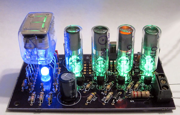
ITS1A thyratron display clock, normal operation.
The Tubes
Clocks using gas tube displays have become popular in recent years. By far the most popular tubes for this type of project are purpose-built neon displays, typically identified by the trade names "Nixie" or "Panaplex". Nixie and Panaplex tubes differ in construction if not in purpose; a Nixie utilizes numeral-shaped wires suspended in a bulb of neon, whereas a Panaplex display uses segmented bars to form a seven or 16 segment character inside of a flat glass sandwich filled with gas. The first such commercial Nixie display tube is widely considered to be the National Union GI10, shown above, which was crude to the extreme and very difficult to control. Later Nixies, designed primarily by Burroughs, were were much more robust and became the genesis for a significant display tube industry in the 1960's and 1970s. Panaplex displays, which were invented as a competitor and replacement to Nixie tubes, are a more reliable and easier to manufacture analog of neon display technology and are still used in modern times in some special applications.
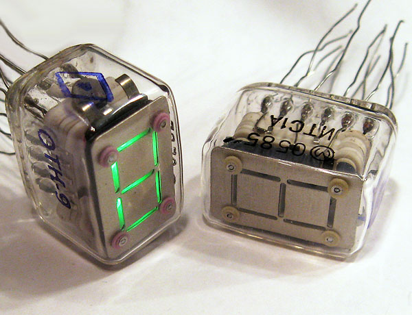
However, even in a world clogged with myriad Nixies and other tube based displays, the ITS1A display tube is without peer. Manufactured by the Soviet Union at the height of the Cold War, the ITS1A is a neon display tube that is ripe with contradictions. Unlike nearly every other neon display known to mankind, which require control signals in the hundreds of volts range to activate, the ITS1A can be hooked directly to a microcontroller and run with TTL level 5 volt signals. This is possible because the ITS1A contains seven tiny thyratrons, one for each segment, which preform the level shifting to control the 300 volt signals needed to ionize the gas inside the tube. Even stranger, the ITS1A is a neon tube that does not light with the orange glow of neon gas as nearly every other cold cathode display does, each of the tubes display segments is a phosphor-coated cup that is illuminated by electron spatter from the control thyratrons. In operation and when viewed from the side this tube actually lights in three colors; orange from the neon ionization, blue from the electron paths inside the thyratrons, and green from the phosphor coating in the digit segments. The anxious collector will quickly discover that this tube is harder to find than an honest Congressional candidate, it's a rare beast even in the current Russian Federation, and for a Western collector it might as well not even exist. I was very lucky to acquire several ITS1A tubes in a private transaction several years ago, and the tubes sat in my parts box since, mocking me with their utter alien-ness. I felt I had no choice but to build something using one of these most unusual display devices.
ITS1A pin connections. All segment signals are at 5 volts.
The ITS1A is, unfortunately, a poorly documented tube with some rather extreme power supply requirements. An exhaustive search of the Internet for information turned up nothing but a crudely scanned Soviet-era datasheet, in Russian, in the Cyrillic character set, written at a time when saying any of the preceding out loud would get you thrown in a military prison camp as a possible Communist-collaborator. In vain I tried scouring the Russian electronics forums with the help of Google Translate, but the only thing I learned was that, judging by the Mad-Libs-style quality of Google's Russian to English translation, a nontrivial portion of the Google Translate programmers are deathly afraid that it is still possible to be thrown in a military prison camp as a possible Communist-collaborator if your knowledge of the Russian language is anything greater than absolute zero. In the end I resorted to manually translating the critical parts of the datasheet as best I could and building a test circuit based on my, admittedly terrible, datasheet translation. I discovered that the ITS1A requires three different supply voltages to bias the various parts of the thyratrons; rated at -300v, 100v and 50v respectively. Once these conditions were met however, the tube consistently and reliably triggered when the segment control lines were connected to a microcontroller. Given the rarity of the tube and the fact that I had no idea how long an ITS1A would function when under power, I opted to go with a single digit clock design. The time is displayed sequentially on the face of the tube, one digit at a time, which would allow a full clock to be constructed using a single tube.
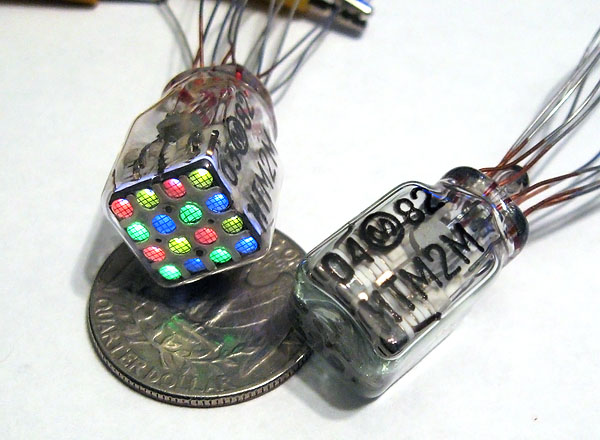
Melz ITM2-M four-color indirect discharge display tube, all dots activated.
The single digit clock design required four point indicators in addition to a seven-segment display, these indicate which digit is being displayed. I wanted to keep the clock's display all tube, and after choosing such an exotic display tube for the seven segment indicator, I had to find something equally unusual to use for a digit position indicator. Initially I experimented with shoehorning an ITM2 thyratron matrix tube into this function. The ITM2 is a small Russian cubical gas display which contains an array of 16 phosphor coated dots, arranged in a four by four matrix. The ITM2 functions on the same principles as the ITS1A tube but requires a higher triggering voltage of about 10 volts DC for the internal thyratrons. ITM2 tubes are not outrageously expensive when they are available, but they are rather hard to find; the only ones I had available were the four color RGBA versions, which clash horribly with a green seven-segment display.
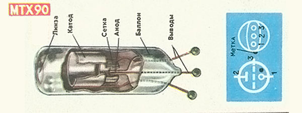
MTX90 promotional material, showing cutaway diagram of tube components.
Ultimately I opted to use four MTX90 thyratrons for the digit position indicators. The MTX90 is a small neon filled thyratron designed specifically for use as a latching indicator, and has a curved glass magnifier incorporated into the top of the tube envelope. The MTX90 was used in a myriad devices in the former Soviet Union, and a causal Google search will turn up examples of the tube lurking in everything from wall switches to quackery-medical skin care lamps. Though MTX90 tubes are not often seen in electronics projects in the West they can still occasionally be bought on Ebay for not-totally-horrific prices and proved to be a good choice to maintain an all thyratron display for this clock.
MTX90, normal operation and control scheme.
The MTX90 has three leads, an anode, a cathode, and a control electrode. When a potential of around 120 volts is applied between the the anode and cathode and a voltage pulse is applied across the control electrode, the tube will lock in the lit "on" position until power is removed. I had hoped that the MTX90 would trigger on a low enough voltage to allow it to be directly connected to a microcontroller, but alas, in my tests I was unable to get the tubes to trigger with anything less than a 40 volt pulse to the control electrode. Interestingly, the tube will trigger on less than 1 volt if the polarity is reversed and the central anode is used as the cathode, but it would probably be a poor idea to run the tube continuously like this. The cathode of a gas-filled tube slowly erodes when in operation, and the anode pin of the MTX90 is so small that it would likely disintegrate faster than a snowflake in a volcano if one tried to use it as a cathode electrode. In the end I used a simple transistor driver commonly used in 'Nixie' style neon clocks, a MPSA42 high voltage transistor is placed across the cathode and connected to the microcontroller through a 10k resistor; not a particularly interesting control scheme, but it works reliably.
| Construction |
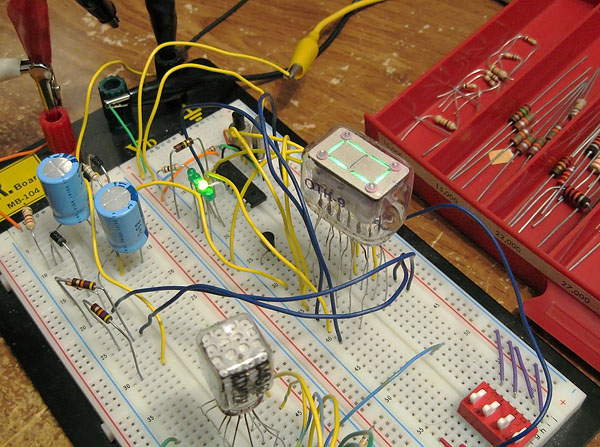
Breadboard test of ITS1A control scheme. Note the cubical ITM2M display at the bottom of the photo, a failed attempt to use a gas matrix as a digit position indicator.
I assembled a prototype of the final clock circuit on a breadboard to test the control scheme for the ITS1A and MTX90 tubes prior to committing to having a PCB fabricated. The controller is a run-of-the-mill PIC 16F628, a cheap, if somewhat long in the tooth model of microcontroller. The software is the same as that used in this DTF104B clock project; numbers are displayed sequentially on the ITS1A tube while the current digit position is indicated by starting a glow discharge in one of the MTX90 tubes. The timebase is a standard quartz crystal with a small trimmer capacitor to adjust the clock frequency for ambient temperature levels. I also included an LED that toggles every time the minutes' digit is advanced... this makes it much easier to set the trimmer capacitor that controls the CPU clock.
ITS1A clock, PCB and board layout.
I made a custom printed circuit board in Eagle, a popular CAD program targeted at PCB layout, and had it made as part of a Dorkbot PCB run, which is a popular service for having small numbers of PCB's manufactured cheaply. The board color schemes for Dorkbot PCB runs change periodically; at the time I ran this batch of PCBs the boards were covered with purple soldermask and came with gold traces. In the grand scheme of things, purple and gold is not a bad card to be dealt in the PCB color gamble, it is a fair shade better than a boring green PCB with tinned traces after-all.
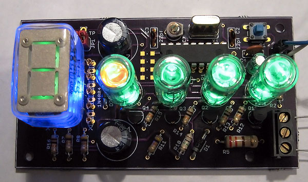
Clock, or science-fiction spaceship component?
The final assembled device turned out looking rather well, and has proven impossible to ignore to all those who have seen it. All of the tubes have bright LED underlighting to increase the 'bling' factor; the ITS1A tube is lit with an epoxy blue LED and the MTX90 tubes are lit with 505nm green LED's. With all of the LEDs and tubes flashing at once, this clock more resembles a prop from an episode of Stargate than something that would be used for the comparatively mundane task of telling time.
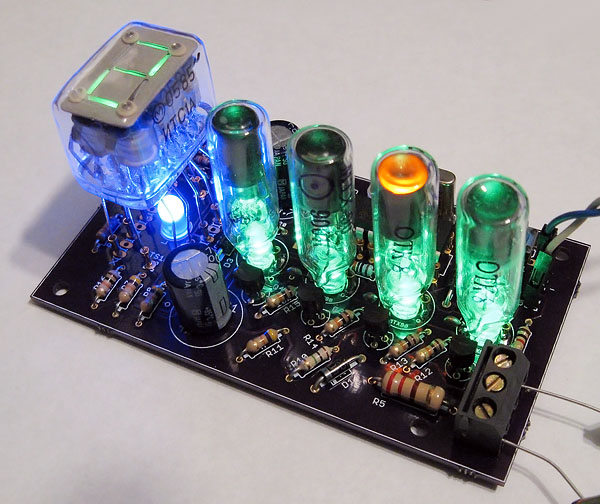
ITS1A clock, finished object.
| ©2000-2026 Industrial Alchemy. All rights reserved. | Switch to desktop version | Contact | |  |