THIS DEVICE IS DIRECTLY CONNECTED TO HOUSEHOLD LINE CURRENT AND IS CAPABLE OF PRODUCING DANGEROUS OR LETHAL ELECTRICAL DISCHARGE. NEVER ATTEMPT TO MOVE OR RECONFIGURE THIS DEVICE WHILE CURRENT IS APPLIED. CAPACITORS IN THIS DEVICE HOLD A CHARGE INDEFINITELY UNTIL MANUALLY DISCHARGED BY A QUALIFIED TECHNICIAN. ALWAYS PLACE THE DEVICE ON A NON-CONDUCTING SURFACE. THE MANUFACTURER AND VENDOR ASSUME NO LIABILITY FOR INJURIES, DEATH OR PROPERTY DAMAGE AS A RESULT OF THIS DEVICE'S USE OR MISUSE.
Device Overview
The Yilane Systems YS-610 Universal Dekatron Computer is an advanced computerized dekatron driver, designed to test and demonstrate various dekatron-style glow transfer counting tubes by generating multiple eye-catching display patterns within a wide range of common dekatron types. The YS-610 is built upon a Microchip 16F84A PIC microcontroller, which has been programmed to generate a number of different spinning, stepped and pendulum-style patterns by sending controlled pulses to the dekatron's guide pins. The user can select a pattern or set the unit to automatically cycle through available patterns, changing every few seconds. The speed at which the tube spins can also be set by the user.
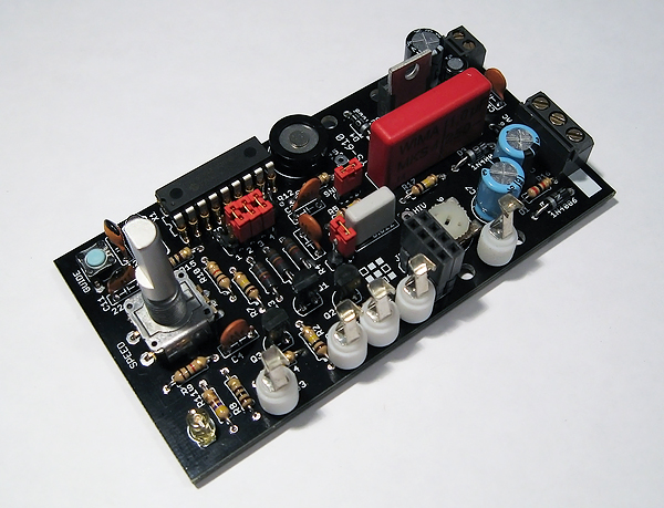
YS-610 Universal Dekatron Computer.
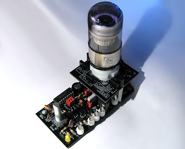
YS-610 Universal Dekatron Computer, shown with YS-61 socket plugboard and Anod OG3 high speed dekatron.
The YS-610 is the successor to our flagship YS-601 dekatron computer, and has all of the features of the YS-601, while adding a rotary encoder for speed control and various code improvements. Unlike the YS-601, the YS-610 is available in a user-assembled kit version.
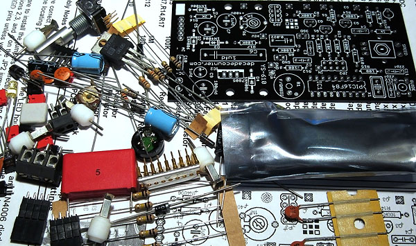
YS-610 Glow Transfer Computer, kit components.
The YS-610 is a quality piece of test hardware, capable of driving virtually any kind of dekatron. The electronic limitations of the YS-610 prevent it from driving oddball dekatrons with highly unusual voltage profiles, such as the Sovtek OG-8, but it will drive virtually any two- or three-guide dekatron, including the 6476/6476A, 6802, 6909, 6910, OG-3, OG-4, OG-7 and A101. It will also drive the GC10B and all of its siblings and clones.
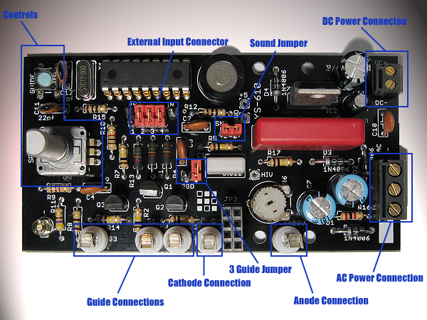
YS-610 PCB layout.
Since the YS-610 uses a 16F84A PIC microcontroller, it is capable of being reprogrammed with a PC and a minimal amount of commonly available programming hardware. We suggest that the user buy their own PIC chip to program on, instead of overwriting the pre-installed chip and consequently erasing the default program.
Functions
Speed Control: Rotating this knob will increase or decrease the speed of the displayed pattern. The maximum speed that can be generated by the pattern generator is 3 kHz, though counting speeds in excess of 500 kHz can be achieved by attaching the device to an external clock source. It should be noted that some dekatrons like the OG-4 can only count at speeds of 2 kHz or less. If you are driving an OG-4, the displayed pattern will become unstable if the device is increased to its maximum counting speed. The minimum counting speed supported by the pattern generator is around 1 Hz.
Mode Button: Pressing the shaft of the speed control downward will sequentially select between one of the YS-610's seven different spinning patterns. The device also has a shuffle mode which will change the displayed pattern once every few seconds. To activate the shuffle mode, press the mode button until you have cycled through all of the patterns. The device will sound a differently-pitched beep when it has reached its last pattern.
Guide Control Button: This button will switch the unit between two-guide mode and three-guide mode. After pressing the Guide button, the unit will emit two beeps if it has been switched into two-guide mode, and three beeps if it has been switched to three-guide mode. When changing modes, the '3GD' jumper should be placed when using a three-guide tube and removed when using a two-guide tube. If pressed a third time, the Guide button will put the unit into single input pulse mode, for using an external clock source. The unit will beep once when put into single pulse mode. Pressing the Guide button again will switch the unit back into two guide mode. Pressing the Guide button will also force the unit to save the current settings to flash memory. The unit will automatically save its settings after a few minutes of inactivity.
External Pulse Interface: The YS-610 provides an external TTL-level interface, labeled J2, which allows the user to connect the unit to a word generator or other waveform source and perform various speed and 'torture' tests on a given dekatron tube. The external interface will override the onboard pattern generator when in use. To use the external input header, remove the jumper blocks from J2 and connect a clock source.
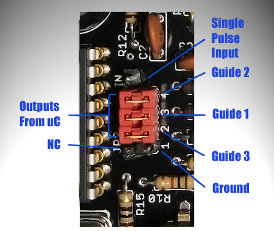
YS-610 external pulse interface, connection diagram.
Sound Function: The unit has a small board-mounted speaker that will softly 'click' every time the dekatron completes a full step. As spinning speeds increase, the clicks turn into audible tones, which can produce some unusual effects with certain spinning patterns. The speaker also sounds various status tones for button presses and mode changes. Removing the SND jumper will disable the unit's speaker.
Reset Procedure: If the YS-610's memory becomes corrupted, the unit can be reset to its factory defaults. To reset the unit, hold down the Guide button while powering up the unit. Once the memory reset is complete, the unit will sound a series of four tones to indicate success.
Power Connections
For this device to operate, the user must supply a 9-12VDC supply to power the YS-610's logic circuitry, and a 110VAC supply to power the anode of the dekatron. A common DC 'wall wart' power supply can be bought anywhere for less than $10, or you can use a 9V battery to supply the necessary DC voltage. The AC voltage can be supplied by a wall outlet in the United States and other countries that operate at 110VAC, or by a step-down transformer in countries that operate at 220V. When making the power connections, be sure to observe correct polarity and to connect each power supply to the proper connector on the board, as a reversed connection could destroy the device.
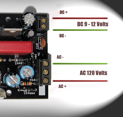
YS-610, power connections.
To prevent accidental destruction of the device when powering it up for the first time, only power up the DC power supply and leave the AC line disconnected. If the DC line has been connected correctly, the power indicator should light up and the buzzer should begin make regular clicking sounds, indicating pulses sent to the still unpowered dekatron. Next, connect power to the AC line only and leave the DC line disconnected. If the AC line has been connected correctly, the dekatron should display a single stationary cathode glow on one of the pins in its counting ring. If both of these tests are successful, than the power supplies are correctly connected.
The Socket Plugboard
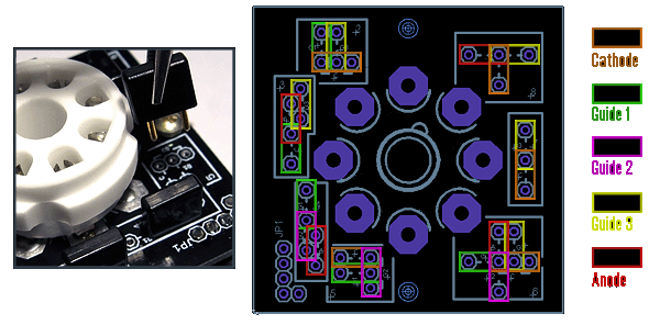
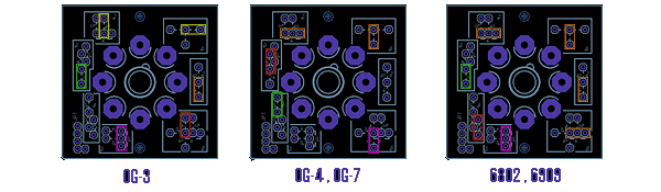
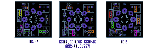
YS-610 octal socket plugboard, possible configurations.
The YS-610's octal socket attachment contains a plugboard that allows the device to be reconfigured to be pin-compatible with virtually every type of octal dekatron, without tools. Movement of the black plugs on the PCB allow the signals from the YS-610 to be routed to pin receptacles on the octal socket as needed to match the pinout of the attached dekatron. Plugboard configurations for most readily available octal base dekatrons are shown below.
Tuning for Different Dekatrons: Variable resistor R6 can be adjusted to provide stable counting with both argon and neon filled dekatron tubes. To set variable resistor R6, use a small screwdriver to turn it counterclockwise until the arrow on top is pointing as far to the right as it will go, then power up the unit with the target dekatron attached and slowly turn R6 clockwise until the tube's spinning stabilizes.
Example Code
For those who want to flash their own programs for the device, here is example code that demonstrates how to spin the dekatron tube left or right. The example code is for a PIC 16F84A, which the user can buy from various retailers. The user should purchase a blank 16F84A instead of trying to re-flash the microcontroller already installed in the device, as doing so will permanently erase the built-in software.
; File dekatrondemo.ASM
; Assembly code for PIC16F84 microcontroller
; Spins a two guide dekatron towards G2.
; Guide outputs are RB1, RB2
; Copyright 2009 Anubis.
;
;
processor 16f84
;----------------- Declare variables
J equ H'1F' ; loop
K equ H'1E' ; loop
SPEED equ H'22' ;spin speed
; Code
org 0
;----------------- Setup the ports
movlw B'11111000'
tris PORTB
movlw B'00000010'
movwf PORTB
movlw B'00000000'
tris PORTA
movlw B'00000001'
movwf PORTA
;----------------- Set the speed
movlw D'100' ;how fast to spin
movwf SPEED ;
;----------------- Step the guides one position
;----------------- change xpulse to xpuls2
;----------------- to change direction.
mloop: call xpulse
;----------------- Waste time by running loops
bloop: movfw SPEED ; w := speed variable
movwf J
jloop: movwf K
kloop: decfsz K,f
goto kloop
decfsz J,f
goto jloop
goto mloop ; Go back and step guide again
;----------------- get states of g1 and g2 and spin towards g2
xpulse: btfss PORTB,1 ;G1 zero?
goto g2t ;check G2, else check G2
btfss PORTB,2 ;G2 zero?
goto g2s ;then turn on G2
bcf PORTB,1 ;G1 and G2 on,turn off G1
goto gend ; and go to the end
g2s: bsf PORTB,2 ;G1 on, G2 off,turn on G2
goto gend ; and go to the end
g2t: btfss PORTB,2 ;G2 zero?
goto g1s ;then turn on G1
bcf PORTB,2 ;G1 off, G2 on,turn off G2
goto gend ; and go to the end
g1s: bsf PORTB,1 ;G1 and G2 off,turn on G1
gend: return
;-------------------- get states of g1 and g2 and spin towards g1
xpuls2: btfss PORTB,1 ;G1 zero?
goto rg2t ;check G2, else check G2
btfss PORTB,2 ;G2 zero?
goto rg2s ;then turn on G2
bcf PORTB,2 ;G1 and G2 on,turn off G2
goto rgend ; and go to the end
rg2s: bcf PORTB,1 ;G1 on, G2 off,turn off G1
goto rgend ; and go to the end
rg2t: btfss PORTB,2 ;G2 zero?
goto rg1s ;then turn on G1
bsf PORTB,1 ;G1 off, G2 on,turn on G1
goto rgend ; and go to the end
rg1s: bsf PORTB,2 ;G1 and G2 off,turn on G2
rgend: return